
SkyBandSemiconductors Discuss your project
RFIC / MMIC design services · Normandy, France

RFIC & MMIC design for demanding RF / mmWave programmes.

When a specification looks out of reach and others stop, that is where we push the limits of RF performance.

Tight specifications, difficult bands, aggressive budgets: that is our starting point. We design power amplifiers, LNAs, switches, beamformers and front-ends from requirements to tape-out-ready layout and measured demonstrator, as an extension of your team or as your full design partner.

European design, outside ITAR scope — No US-controlled IP.

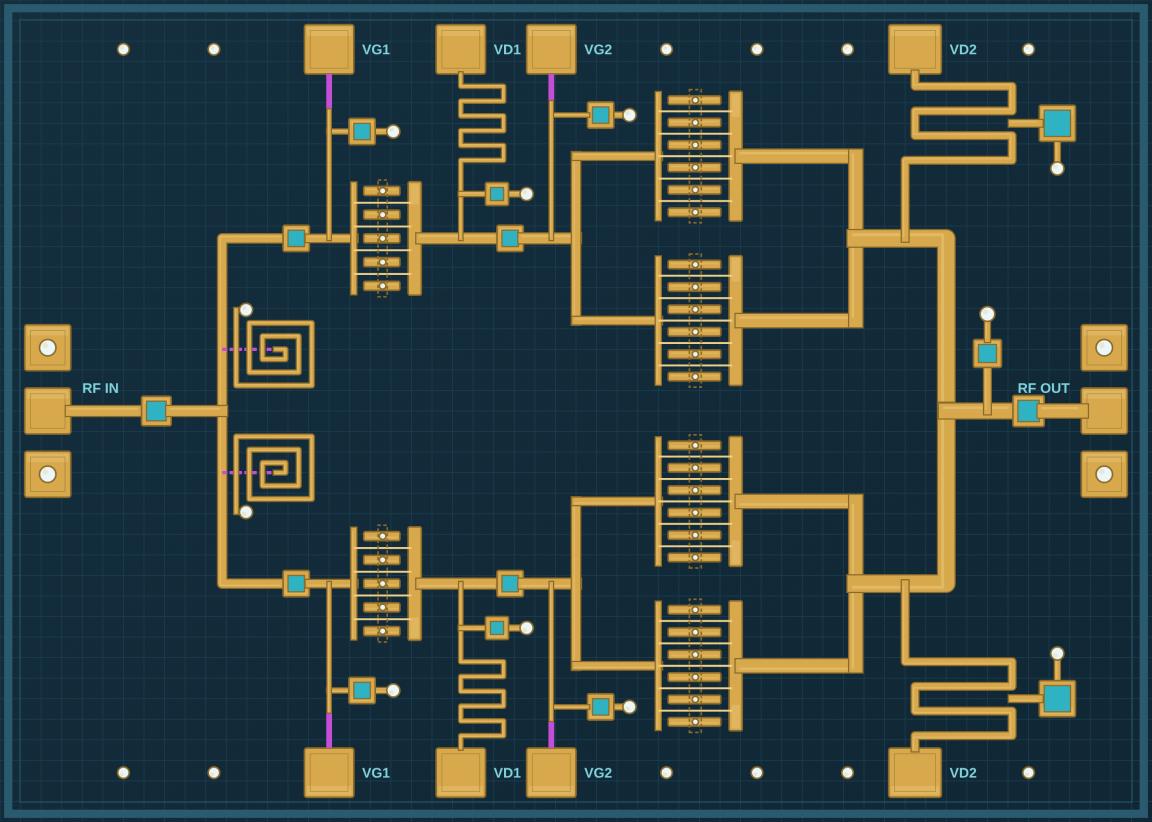
Illustration of a GaN PA MMIC layout, with RF input and output and gold circuit structures on a dark background
Illustration of a GaN PA MMIC (top view)
2 PhDsin the founding team70+ yrscombined experiencesub-6 → 100 GHzdesign experienceGaN · SiGe · RF-SOItechnologiesITAR-freeEuropean design
What we do

Four ways to work with us

Your RF & mmWave front-end, designed with your team.

02

Circuit design projects

A complete block: specification, design, layout, verification, tape-out-ready GDS and design report. Fixed-price work packages can be agreed after scoping.

Best forA block with a clear specification and a defined hand-over to your team.

Explore this service
04

R&D programme partner

Proposal writing and work packages for ESA (ARTES, TDE), EDF and CNES / France 2030 programmes.

Best forConsortia preparing ESA, CNES, EDF or France 2030 proposals and work packages.

Explore this service

Time & materials, fixed-price work packages or co-development — with confidentiality and IP arrangements agreed for your project.

From idea to demonstrator

A quality demonstrator, on a clear schedule.

With European foundries and partner labs where available, within an agreed programme.

  1. Kick-off: Scope and acceptance criteria agreed
  2. Pyrite: Most promising solution selected
  3. Bronze: Concept frozen
  4. Silver: Schematic and layout frozen
  5. Gold: GDS frozen at tape-out
Design maturity · kick-off to tape-out

The design is refined like a metal.

Each gate freezes one deliverable, so nothing already validated is reopened. Gold means the GDS is frozen and ready for the foundry run at M3.

  1. Kick-off

    Scope, interfaces and acceptance criteria agreed with your team.

  2. Phase 1: Feasibility

    Feasibility report and recommended line-up

    State of the art, line-up, budgets, first simulations

    Milestone M1Go / no-go review

  3. Phase 2: Design

    Verified design database

    Schematic, EM, layout, DRC/LVS, design reviews

    Milestone M2Design review

  4. Phase 3: Tape-out (MPW)

    Tape-out-ready GDS on an MPW slot

    Multi-project wafer runs, with European foundries where available

    Milestone M3Sign-off review

  5. Phase 4: Packaging & test

    Packaged parts and test data

    Assembly, S-parameters, power, modulated tests

    Milestone M4Test review

  6. Phase 5: Demonstrator

    Measured demonstrator and design report

    Measured hardware and full design report

    Milestone M5Final review

  7. Final report

    Design report and measured results handed over to your team.

Every project is different: timelines depend on the technology, the frequency band, the circuit complexity and the foundry MPW calendar. After a first technical discussion, we give you a step-by-step schedule aligned with your programme milestones.

Discuss your timeline
Our design toolbox

One RFIC / MMIC design flow, three verification loops.

Applied to power amplifiers, LNAs, switches, attenuators, phase shifters, beamformers and complete front-ends.

  1. Requirements & architecture

  2. Technology & device selection

  3. Circuit design

  4. Layout & EM

  5. Verification

  6. Sign-off & tape-out

  7. Test & validation

    After the loops: measured hardware against simulation

Loop 1 · Concept

Schematic with realistic models and finite-Q passives

Steps 1–3
Loop 2 · Implementation

Layout with RC extraction and cascaded EM blocks

Steps 4–5
Loop 3 · Sign-off

Top-level EM and top-level RC simulations, final optimisations

Step 6, before tape-out
Design review at the end of each loop

Held with your engineers, so you keep full visibility and can steer the design before each step.

Explore the complete design flow
Application areas

RF engineering in context.

Satellite links, radar, active antennas and millimetre-wave networks.

Frequency coverage by application
  • Satcom: X, Ku and Ka bands
  • Radar & defence: UHF to Ku, X band first; airborne radar and spaceborne SAR
  • Active antennas: all bands, band-agnostic beamforming architecture
  • 5G / 6G: millimetre-wave, up to 100 GHz
Indicative frequency coverage of the application areas we target; not performance data.
A satellite with solar panels and a dish above the Earth at dawn, with the words satellite, connectivity, observation and exploration.
01

Links, terminals and payloads in low and geostationary orbit.

NeedTerminals and payloads need enough RF power at the antenna and a receiver that adds little noise, within tight size, weight and power limits.

RF contributionThe RF front-end: power amplification, low-noise reception, switching and beam-steering control.

XKuKa
A satellite, an aircraft, a ship, a ground station and a ground radar linked by radio beams over a night view of Europe, illustrating radar and aerospace RF links.
02

Ground and airborne radar (X-band first), spaceborne SAR imaging, defence radios and multi-band front-ends under strict SWaP constraints.

NeedA radar or defence radio transmits high power and still has to receive very weak signals, within tight size, weight and power limits.

RF contributionThe transmit/receive RF front-end: power and low-noise amplification, switching and receiver protection.

UHF → KuX priority
A flat active antenna array on a rooftop forming several radio beams above a city and a river.
03

Beamforming, transmit/receive functions and electronically steered tiles.

NeedAn electronically steered antenna must fit a small element spacing, stay matched across RF paths and remove its own heat.

RF contributionThe transmit/receive RF paths and the beamformer behind the radiating elements, with calibration and thermal design in view.

Band-agnostic
A mobile network tower with several antennas above a city and a river, with radio beams arcing over the skyline and the words connect, cover, scale and empower.
04

Millimetre-wave radios for base stations, small cells and fixed wireless links.

NeedMillimetre-wave radios need linear, efficient RF power and a quiet receiver in a compact, cool unit, with many channels in parallel.

RF contributionThe millimetre-wave RF front-end and beamformer. 5G is the current target; 6G is an exploratory direction.

mmWaveNTN
See all application areas
Working together

Your questions, answered.

Can you work under our NDA?

We can discuss your NDA and agree confidentiality and IP arrangements before technical work begins.

Which technologies do you design in?

GaN, SiGe BiCMOS, RF-SOI and CMOS, with European foundries where possible.

How fast can you start?

We confirm availability and a proposed start date after a first technical discussion.

Do you sell chips?

Not yet — we’re building our product line. See our roadmap.

Start a conversation

Free first RF feasibility review

An initial discussion of your application and engineering needs, with no obligation and no transfer of intellectual property. Do not submit confidential, proprietary or controlled data. Select the review in the subject list to request a meeting.

Start your enquiry